Empous, the Empire Simulation Game
SoyBot, a Ground Vehicle for Soybean Phenotyping
Westhampton Library Maker ClubThis is a butler-style robot that takes orders for food and drink and delivers them to you.
Design
Origins
I originally started this as a project with my college friends. As engineering students, we were into pretty nerdy topics. One time when we were hanging out, the idea came up of building a robot. Although it started out as just a fun idea, we eventually convinced ourselves that we had the skills to really make something like this happen. Once we committed to actually doing it, we designed a robot that could do the following:
- Prepare mixed drinks and deliver them from a home base to the users’ locations
- Provide a basic user interface
- Be able to navigate an interior space and avoid obstacles
- Be built from scratch wherever possible (avoid using kits)
With those basic ideas, we came up with a list of parts, including motors, a battery, and some valves. The design was really nothing more than some components and the belief that all the integration would come to us naturally. Here is the list of components that we bought:
- 1 x 12V Lead Acid Battery
- 2 x 322HD Hobby Servos
- 2 x 12V Jameco DC motors
- 2 x Maxbotix Ultrasonic Rangers
Some Added Perspective
After a lot of work on the project, but not a lot of progress toward a concrete goal, I added some more extensive design information. First, I created a set of goals and requirements for the project:
Objectives
- Offers variety of food and drink
- Delivers items on demand
- Navigates throughout home
- Maintains self when not engaged
Performance Requirements
- Ordering system available via any web browser on network 24/7
- Delivers order within 1 minute
- Delivers to at least 10 predetermined waypoints
- Offers 2 drinks and 4 types of food
- Provides current status of pantry
Non-functional Requirements
- Does not spill food
- Stops when an obstacle is in the way
- Can navigate variety of terrain: carpet, wood floor, tile, thresholds
- Is pleasant to be around/has personality/makes funny quips
- Recharges battery automatically at home base
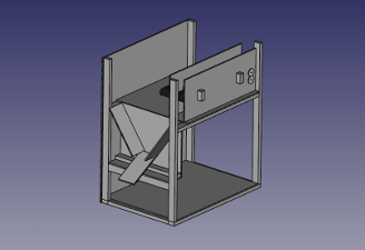
Next, I created a cyber-physical architecture to identify all the subsystems and components and clarify how they interact with each other:
Finally, I created a work breakdown based on the requirements and architecture that lays out exactly what work needs to be done in order to see the project through to completion. I converted this directly into a schedule so I have deadlines to ensure I stay on top of everything. You can see the spreadsheet here: work breakdown.
Build Log
2010
It all started late at night in my college dorm in Troy, NY. Some friends and I were hanging out, goofing around, when the idea of building a robot came up. We were smart engineers, we knew how these things worked–how hard could it be? I was of the mind that once we had all the components, the robot would pretty much assemble itself, so we started laying out some plans. See the design section above for more info. In retrospect, we had no idea how long a project like this would take and how expensive it would be.
As poor college students, we didn’t have nearly enough money to buy all the parts we decided to get. We brainstormed and came up with the idea of funding the project by redeeming beverage containers on campus (as there was no shortage of those). Using that money and some small contributions from our own pockets, we bought servos, DC motors, and a battery.
In parallel, we were on the lookout for some scrap that could be repurposed into the chassis. At the time, I was working in a lab at the Lighting Research Center. They had a bunch of old parts lying around that needed cleaning up, including a steel box from a fiber optic project. Since it was already headed for the scrap pile, they said that I could take it home. After pulling out and discarding the leftover components, we had the start of a robot.
In order to attach the DC and servo motors, we needed to prep the box a little. We could easily drill holes for the mounting screws, but we needed a slot cut in the box that could hold the servo. We asked at one of the machine shops on campus, and they suggested we cut it out on the plasma cutter. Since it was such a simple operation, they were able to program and cut it up in a few minutes. This was the first time we got to see the plasma cutter in action and it was pretty rad.
Despite the progress we made, we didn’t get to really put all the components together into a functional platform. Also, I ordered valves for the drink dispenser, but some mixup resulted in them never getting delivered, so the drink mixing component unwittingly took a backseat to the mobile platform.
Sometime between 2011 and 2014
After I graduated college, I used my spare time to design and build the initial steering hardware. I didn’t know much about different steering designs, so I attempted to imitate the rack and pinion style on a car, but with a servo motor attached directly to the rack in place of the gears:

It was pretty naive, but my goal was simply to get the robot driving around.
It was around this same time that I discovered Solid State Depot (SSD), my local hackerspace. I was pretty enthralled by the awesome tools and people there. They also had raw materials, including a few scrap pieces that I used to start building my robot’s steering.
The first component I worked on was the piece where the wheels attached (part B in the diagram). I found a small piece of steel, cut it into the right shapes, and drilled the holes I needed. However, SSD didn’t have a set of taps at the time, so I wasn’t able to add the threads I needed.
For the next part of the story, we need to take a little detour. Boulder, Colorado is an eclectic place with lots of interesting treasures to discover. One of those unique aspects is McGuckin Hardware. If you ever go to Boulder, you really should visit this establishment. Sure, it’s a hardware store, but it feels like a disservice to describe it as just that. They have all the typical goods and services, but it’s infused with a local flavor that is really unlike any other hardware store I’ve been to. One of the services they offer is simple machining. Since I needed some threads cut in my steering parts, I decided to give them a shot.
The person I interacted with was more than happy to help me out, but the results were not very good. Either the particular piece of steel that I pulled out of the scrap pile was harder than expected, or he simply wasn’t prepared to cut it, but the tap broke off in the hole. It felt like a setback. But then, the manager of the shop gave me contact info for a machinist who might be able to help me out using his personal shop. I hadn’t ever tried something like this before, but, hey–why not?
I called the fellow and arranged a time to swing by. He lived in a trailer toward the outskirts of town and his entire shop was inside a small (probably 6ft x 10ft) shed next door. The entire thing was packed tight with all his tools, and it was obvious that he had been doing this for a while. He took a look at the piece, pulled out his tap set, and got to work. It turns out that, sometimes, all you need to get things done right is some experience and a little patience. I settled up, thanked him for his help, and headed home with my freshly-machined pieces. Looking back on it later, it was really a pretty neat experience.
Around the same time, I bought some motor driver circuit components and got the motors spinning via an Arduino. Because one of the goals of the project was to build things from scratch and avoid kits, I chose to buy an L298 H-bridge chip and assemble the circuit myself on a solderless breadboard. You can see the result here:
To finish out the steering components, I pulled the wheels off an RC car and bought some steel rod and connectors at–you guessed it–McGuckins. A little assembly and the robot was finally on the move:
As you can probably tell, the steering hardware was pretty shoddy at this point. I think it’s safe to describe it as a “learning experience.”
One main issue I ran into during this phase was the weight of the robot. The steel box and lead acid battery put some real strain on the drive motors and steering hardware. Once again, McGuckins came to my rescue in the form of a new chassis, which was a plastic box. In addition to being much lighter than the steel one, this box allows you to see what’s happening inside, which is kind of cool.
Two more important aspects of the robot developed in this timeframe. First, I replaced the wheels on the robot with a nicer set (https://www.pololu.com/product/1430), since the RC car wheels were damaged when I installed them. Second, I decided to add a little obstacle avoidance to the robot. The sensor I chose is an ultrasonic range finder from Parallax: https://www.pololu.com/product/1605. But truly, the most important thing that I added was the mount for the ranger.
I wanted to mount the ultrasonic ranger to one of the servos so that the robot could move it around while driving. This was a perfect application for a 3D printer, and SSD happened to have a couple that I could use. There were designs for this part online, but they weren’t available for free. I always enjoyed doing 3D modeling in school, so I decided to design and print my own.
This was the first time that I used a 3D printer and–let me tell you–it was truly exhilarating. You might think I’m exaggerating, but I really was so excited by this interaction that I couldn’t stop thinking about it for the next couple weeks. There was just so much power in the notion that I could imagine a part in my head, design it in CAD, and have a prototype on my desk within hours. It also was one of the first new skills that I learned from a fellow member at SSD. I have come to believe very strongly in the importance of sharing our skills and knowledge with others, and this experience is at the heart of it.
After a few iterations, the ultrasonic ranger was mounted and ready to go:


April 24, 2014
Over the last couple years, I’ve more involved with SSD and got distracted by other projects, such as my binary clock. But now I’m finally getting back into working on the robot. The 2 areas I’m focused on right now are redoing the steering hardware and finalizing the circuitry. Now that I have access to 3D printing, I’m going to try to build a more-polished steering system that uses the same basic design as the old one.
Here are a couple pics of testing the motor driver circuit and (finally) soldering it to a real circuit board:


March 13, 2015
Although I haven’t posted about the robot in some time, I’ve been making some small progress in the last year. Mostly, I’ve 3D printed the new steering assembly:


Currently, it’s really a piece of crap, but I am trying to just get the robot back up and running again, then I will work on fine tuning things. In addition, I recently undid the progress in my last post by blowing up the motor driver chip. So now I’m in the process of buying and resolding that circuit. It’s a pain when you do something so dumb, but I guess that’s part of learning:

In general, things are coming together, even with the setbacks, and I think that the robot will be driving again pretty soon.
April 28 2015
As promised, it is working again:
I rewired the driver circuit and hooked up the two servos, plus I did some organizing of components in the box and added some strain reliefs. I also included a key switch, so you have to have the keys to turn it on (and off). I also bought a battery charger so I can have some extended testing sessions without worrying about draining it down too low for long periods at a time.
July 26, 2015
More setbacks recently: I left the robot in the car when I was at work one day and learned that the PLA steering assembly will melt even in moderate temperatures. So I’m going to have to find a long term solution and print a new one in the meantime.

In addition, I hooked up all the motors and sensors in the box and started testing only to find out that somewhere along the line, I didn’t check my circuitry closely enough. When the DC motors were turning, it caused noise in the servo power that made them jitter like crazy.
I have overcome the power issue by rearranging how I ran the power through the system. I originally had a switching voltage rectifier to bring the 12V battery down to 6V, which I was going to use to power the servos and the Arduino. I added a lot of capacitors at various points throughout to try to eliminate the noise in that circuit, but couldn’t beat it. It then occurred to me to try to run the 12V directly into the Arduino, then run the servos off the Arduino’s 5V pin. As it turns out, that was exactly what I needed.
As for the melted steering, I’ll have to wait until I can print a new one. I have some ideas about redesigning it, but I need to think more about how I want to do that.
August 30, 2015
I’ve re-printed the steering. In addition to printing out new parts, the size of the connector piece (what would be the rack in an equivalent rack and pinion design) was too small, so I kludged together a new one out of the multiple prototypes that I had printed already.
With the power and steering figured out, I can finally play around with the programming to see what I can make the robot do. I currently have it performing a basic obstacle-avoidance algorithm that seems to work pretty well. It can drive itself around a room and generally not run into anything. However, I’ve noticed a different problem now. After a minute or two, the Arduino starts to reset every few seconds. If I turn the power off, wait a minute, and then turn it back on, it will run again for a minute and then do the same thing. I think that either the battery is getting worn out or I’m tripping a thermal shutdown–perhaps my power management solution is not really what I needed after all.
October 11, 2015
A couple of updates. First, it was indeed the thermal shutdown on the Arduino that was causing the robot to stall. The fix, as it turned out, was to run the power through the switching regulator (down to 6.5V) and then through a linear regular to get to 5V. That was sufficient to run the servos and keep out the noise from the DC motors.
Second, I was annoyed that the robot was spending so much time waiting in the existing obstacle avoidance algorithm. I wanted it to run constantly, but the DC motors were too fast for the robot to have time to look around with its head servo. I wasn’t sure if I could simply run PWM into the H-bridge circuit, but I gave it a shot and it worked well. The dog isn’t sure he approves though…
I think the robot is finally at the point where I have sufficient hardware built to allow me to focus more on the software and design a little intelligence into it. I would still like to work on the hardware more in the future, but it feels like an accomplishment that it can drive around by itself and looks like a robot, however simple it is.
April 2, 2016
Since the last update, I brought the robot to a local hackerspace and a maker program that I started at the local library. Generally, I have received positive feedback. My only real concern has been that the steering assembly is too weak for the weight of the robot. The lead acid battery really weighs it down.
I thought it was fun designing and building the steering, but in order to keep things moving forward, I replaced the assembly with a simple caster:

While making the code update to implement the new steering, I also changed the algorithm a little. Before, any object caused the robot to back up and turn a specific amount; I added randomness by changing directions when there were no obstacles detected. Now, the amount of time that robot backs up is random, so, after he avoids an obstacle, the new direction he faces is never the same:
Summer 2017
Since my last post, the robot has been on hold for a little bit while I’ve been in school getting my master’s degree in Robotic Systems Development. Now that I’m on summer break, I can devote some time to it again. And, luckily, this means that I can apply some of my new skills to this project.
The main thing that I’ve gained from the master’s program is a perspective on systems engineering. The basic philosophy behind systems engineering is that you should design a system before you start implementing it. This will save you time and money by illuminating obscure issues early and it will ensure that all system components are going towards fulfilling a set of clear system requirements. Without this perspective, projects can tend to get bloated or behind schedule (a symptom I’ve noticed in this project in particular). So, with that in mind, I’ve created a set of design documents that I think will help me complete the robot by the end of next year. You can see the updates in the Design section above.
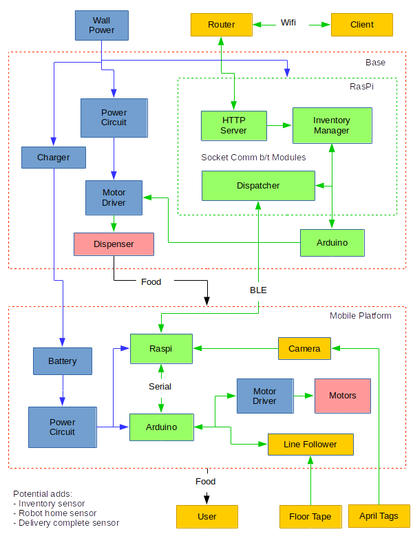
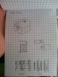
In addition to the systems engineering additions, I have started working on the design for the base station where the food will be dispensed. I drew up a few designs on paper and wrote a bunch of code that makes up the foundational software components of the base station. I am writing it in C++ to build up my skills with that and CMake. All the code can be found on my Github page.
For the mechanical design of the base, I imagine it will basically be a vending machine with some interface for the robot. I started out looking for cheap, small vending machines to purchase, but it turns out that such a thing doesn’t exist. You can certainly buy small vending machines, but they ain’t cheap. So, instead of buying one, I started to think about how to build one. My design is basically a set of parallel conveyer belts that all dump their contents into a chute that empties out onto the robot. Conveyer belts are another thing that are difficult to purchase for cheap, but I managed to find a kids toy that I think I can effectively adapt for my purposes.
On the code side of things, I’m pretty happy with what I’ve written so far. I made a set of client/server objects that communicate with each other over sockets using a simple third-party serialization library. I had never worked with sockets, serialization, or client/server design before, so it was fun to see everything come together. The tools are actually simple enough that I might be able to use them for future projects.
Feb 1, 2018
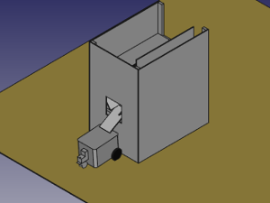
I spent the day today working on the base design. I’ve created a preliminary design in FreeCAD based on my hand-drawn design from last summer:
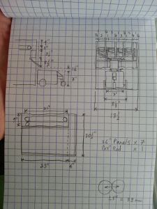
It’s going to take some more time to get the entire design ready because I’m learning FreeCAD as I go.
I also started hacking away at some of the components for the base and robot and found some gaps in my materials or preparation, so I had to order a few parts.
Feb 19, 2018
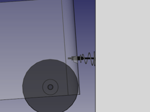
I’ve spent a little more time on the base design. Specifically, I’ve been thinking about how to make a connection between the mobile platform and the base so that the robot can charge itself when it’s not in use. I think that I will use a magnetic connector like the ones used for Mac laptops. The connector needs to have some alignment features, so I’ve added that to the robot side. It will also need flexibility, so I added a compression spring to the base side. This will hold it in place but allow some movement during alignment:
Here’s the full base design with the robot parked in charging position:
The current mobile platform design uses line-following for navigation throughout the house. I purchased a line-follower array from Sparkfun and added it to the Robot. Here is a short clip of my initial testing:
I still need to make a permanent fixture to attach it to the chassis, as it is currently attached with duct tape.
I’ve been running behind schedule a little bit, but I think the project is still on track. Most of the delay is due to postponing component purchases until I have more stability in my day job. Regardless, since adding a work breakdown structure, it has been much easier to keep tabs on my progress and stay abreast of how the project is going overall.
Mar 30, 2018
While waiting to buy parts, I’ve focused on the software components of Robie (I’ve also decided that will be his official name). Because I never had a formal introduction to C++, I set aside some time to read Bjarne Stroustup’s The C++ Programming Language. Even though I knew most of the concepts already, it was nice to get a new perspective, especially that of the language’s creator. I’ve also been studying for technical interviews, which has helped me learn some of the language’s “gotchas.”
After some time away and armed with new knowledge, I looked at the existing C++ code and made some upgrades:
- First, I split the existing repo into separate repos for each component: base software, mobile platform software, and user interface software. You can see the new repos on Github.
- Second, I tore up and replaced some of my simplistic code with some more sophisticated components, especially parts that dealt with C-style strings.
- Third, I separated out the inventory and communication code into a separate library so it was available to be linked to the HTTP server and for any apps that I wrote in the future.
Once I had those revisions complete, I focused on writing the HTTP server code so users could interact with the inventory. I was unsure how to approach this part, since HTTP doesn’t have a standard implementation in C++. I knew I could write a server myself, but I didn’t want to go through such a hassle for something that had already been implemented many times before. I ended up finding a simple server that I could fork to my own.
In making the HTTP server interact with the inventory server, I realized that I really needed to have some kind of administrative interface for checking on and updating the inventory. To create this, I converted my old test client–which was just for debugging the communications–into a full admin client. This revealed a number of issues with my original design, which I fixed up as I went.
Now things are running pretty smoothly. I can connect to the HTTP server from my browser, submit an order, and see the inventory levels change. If I need to edit things, I just need to boot up the admin console and send a few simple commands.
Jul 3, 2018
We moved into a new place so I’ve been setting up my workshop:

I’ve got a lot more room to build, which has helped me make good progress on the home base portion of the project:

You can see one of the conveyer belts that I purchased sitting on top, roughly where it will be when the base is done.
Aug 12, 2018
The design of the power electronics for the mobile platform has been a sticking point because I’ve been unsure of how to approach the battery charging. I envisioned an auto-charging system where Robie would drive up to the base and make some kind of magnetic connection to a charging circuit. But I also wanted to switch battery chemistry from lead acid to something lighter.
I did some light research and discussed the idea with my electrical engineer friend and decided that the added circuitry would be more complex than I had hoped. So I’ve decided to make the auto charging another phase of the project after the current build is done. For now, I’m going to use a NiMH battery and a basic charger that I bought online.
The basic wiring of the mobile platform had always been very messy and fragile, so I decided to reorganize. I’m most of the way done and it’s looking much better:

You can also see that I’ve mounted my line-following board on the bottom of the bot:

Jul 7, 2019
Although I haven’t been posting here, I’ve made a number of updates in the last few months.
First, I did some machining and assembly of the base station. The main takeaway is that typical consumer plastics are difficult to machine. In particular, I had a hard time drilling out the center of the spindles in my conveyor belts. The results are accurate enough to work with, but I may have to redo them (probably a 3D print) in the future. I also tweaked the design a little and used some threaded rod to hold the conveyors together. Here are a couple pictures of what I have so far:


Second, I’ve done some work on the coding side. I rearranged things a little bit to update the style and also to make everything more modular. The coolest addition is Bluetooth communication between the Raspberry Pis; now the base and the mobile platform can communicate with each other. You can see the updates on my Github page.
I’m particularly happy with how the bluetooth worked out because it’s integrated into my existing client/server library. Now users just need to select which type of socket they want to use (IP or Bluetooth) when they connect. The rest works exactly the same way. Pretty slick!
The end result is that the ordering system is somewhat functional. You can see all the pieces working together in this video:
Jan 26, 2020
Every year, I set new year’s resolutions, and I have included finishing the robot project every year for the last 7 years. Last year I felt pretty good about being able to finish everything, since I did a lot of the systems engineering work and had a good idea of what I was trying to accomplish. I made good progress, but still wasn’t able to wrap it up. So I’m trying again this year.
I started this month by working on the coding side. Robie needs some way to figure out where he is so that he can wait at the base station for orders and stop when he gets to his destination as part of the delivery. I’ve had a few ideas for how to do this including RFID or some kind of simple proximity sensor. I decided to try doing it with vision. I decided this because the Raspberry Pi has built-in (and cheap) camera support and because I wanted to try out this type of sensing. In particular, I wanted to learn about how to use apriltags. Apriltags are ubitquitous in robotics and I’ve never used them before, so I thought this would be a good opportunity.
For something as simple as reading an image from disk, I assumed that there would be a very simple library available. As it turns out, the truth is more complicated. There are existing libraries for jpegs, but they are not exactly plug and play. OpenCV is super simple, but it requires building from source on the Raspberry Pi, which includes gigabytes of features that I don’t care about. In the end, I just wrote my own function for reading bitmaps. I didn’t know anything about the format, so it was kind of neat to learn. Of course, it would have been even better to just grab an image from the camera and keep it in memory, but that leads to the other issue that makes this complicated…
Grabbing an image from the Raspberry Pi camera is super easy if you use their command line tool, but the only option for handling the resulting data is to save it to disk. Again, OpenCV would greatly simplify this, but I don’t want all that overhead. I assume that I could figure out how to grab the images directly in my program (especially since the Raspberry Pi app is open source), but I’m leaving this as an area for optimization in the future. At this point, I’ve strung together the different components well enough that I can move forward with testing. As always, the latest updates are on my Github page.
Feb 1, 2020
I’m at the point now where I can basically test the entire system’s functionality. I made a little masking tape track in the basement and have some starting apriltags, plus I added a little extra state management software so Robie knows when he’s delivering an order and when he’s headed back home. It’s a little janky, but it shows off how everything will come together in the end:
Feb 8, 2020
I’ve taken the robot to my local hackerspace, HackPGH. I thought that, by keeping it there, it would be easier to get large chunks of work done since I would have access to all the tools I need in the same place. I also thought that sharing my progress with fellow hackers could be an extra motivator to get things accomplished.
In transporting the components, I realized that they are pretty susceptible to damage from movement, so today I started out by attaching the circuitry to the base of the dispenser:

Then, I cut out and attached some parts of the chute where food will fall when it is dispensed:

Feb 15, 2019
The apriltag processing components are pretty slow, to the point that I’m not sure if they will be reliable in the final product. So today, I went back to the image processing and tried to implement some optimizations. The actual processing side of things (i.e. not the raspistill process) is now split out into two components. One pings the camera to request a new image, then uses ionotify to wait for the image to be written to disk and reads it into memory. The other object waits for the first one to read a new image, grabs it, and does the apriltag detection.
I came up with a triple buffer system to try to minimize contention and improve throughput; each thread works on data in its own buffer, then swaps with a shared buffer in order to exchange data with the other thread. This worked out pretty well, but still isn’t very fast on the Raspberry Pi. The best optimization I could come up with is reducing the image resolution, which decreases tag detection accuracy. This is an area that I will have to come back to again, probably to completely eliminate writing to disk.
Feb 23, 2020
The focus today was on getting the line following working well so I can lay down a full track for testing. The line following hardware works with both a dark line on light background and a light line on dark background. It also has a knob for adjusting the LED power so you can tune it for whatever surface you’re working with. At the hackerspace, we have a light blue floor, so I wasn’t sure which configuration would work best.
I started by testing dark blue painter tape directly on the floor, but it didn’t work too well. I learned that the floor, while being light in color, is acutally pretty absorptive with the IR light. Next, I tried printing out some black lines on white paper and taping them to the floor with masking tape:

Next I tried inverting the hardware to look for a light-colored line and using reflective tape:
This worked pretty well and I think I’ll use this layout in the future. I’ll have to buy some tapes and test them to find out what works best.
The other thing I learned today is that the width of the line is important. If it’s too thin, it can be hard to detect and causes a lot of oscillation, which can turn into instability. A line that is wide enough to be picked up by at least two sensors in the array at once is much better.
Feb 27, 2020
I added some more components to the chute. It’s starting to look pretty good:

May 19, 2020
Just as soon as I started working on the robot at HackPGH, the global coronavirus pandemic hit, and I had to move operations back home. Since I was stuck at home with extra time on my hands, I decided to dive into the issue of the slow apriltag processing:

My first attempt at this was to create a stripped-down verison of raspistill. I didn’t know much about the underlying libraries (primarily MMAL), so it was difficult and slow-going. After spending a few days on this, I decided to take a different approach: instead of using just a few components from raspistill, I would compile it as a library and slightly modify the objects so they could be called from my c++ program.
July 12, 2020
Success! After a couple months of slogging though the camera capture code, I have a new version that grabs images directly from the sensor and detects the apriltags. The new, straight-to-memory approach is much faster, but it has the drawback that, because I wasn’t running the full raspistill program, I had to manually adjust things like exposure and white balance. I’ll have to see how well this works in the final installation location (wherever that may be).
Robie is now set up in the basement on a test track of masking tape:

This is the closest that Robie has felt to completion and it’s satisfying to run a full order through the system.
July 21, 2020
I’ve moved Robie upstairs into our dining room so that I can finally start testing him in a real world environment. The next step will be setting up the track that he’s going to follow. Based on my testing back in February, I decided to build my line out of reflective tape on black paper.
I purchased some 3M reflective tape for the track, and some black construction paper on which to lay it. The tape is really excellent quality and works great. The construction paper, though, is a hunk of junk. I wanted something to absord the IR light, and it turns out that the paper is nearly as reflective as the tape! This was a frustrating discovery, since I had already bought a pack of it and laid about 10 feet of track before testing it.
Luckily, the floors in our house are much less reflective than the tape, so I was able to use the tape exclusively. This was a nice benefit, since it means that the track has a much smaller footprint and will be less disruptive to my wife and I as we walk through the area. It does mean that the track is not as secure, though, since I’m not willing to apply the tape directly to our wood floors.
Aug 2, 2020
There were a number of latent bugs in the system that I had never gotten around to fixing, so I took the time to squash a few of them today:
- Fix saving the inventory to disk whenever it changes
- Load the delivery locations from a configuration file
- Use 1-indexing for the locations, since 0 is reserved for the home station
- Enable dispensing from both of the slots in the dispenser
Aug 9, 2020
Today I built out the entire track using my reflective tape. For now, it runs from the dining room to the living room and back:


I also spent some time tidying up the code. Now, both the mobile platform and base station programs are running as systemd services that will start when the computers boot up, so I don’t have to log in to get things running.
Aug 15, 2020
Today marks 6 weeks before the due date of my first child. This has been a big motivation for me to make progress on Robie this year; I’d like to call version 1.0 of this project complete before the baby gets here, since I know I’ll have another project on my hands then :]
Today I built up a little more of the structure of the base station. Enclosing the base station doesn’t accomplish much in terms of functionality, but it helps the project look more polished (which is good when it’s sitting in our dining room). In previous pictures, you could see that I started using 1/4” plywood to enclose the base, but I don’t have any available right now, so I’m using some foam-core posterboard. I think it looks pretty good:

One undesirable side effect of enclosing the station is that the apriltag marking the station is now very close to Robie when he drives by. He has to be close in order for the dispensed items to fall onto his head, but it makes it very difficult for his camera to catch the tag. So he will often just drive right past when he’s on a return trip. I’m going to have to brainstorm this one a little bit. I have a couple ideas, but I’m not sure which one is best.
I also took a little time to move Robie’s internal wiring around so that I can put the battery inside and just expose a power switch on the outside (the keyswitch that I was using a few years back has since been removed, since it was kind of bulky). However, when I did this, the “eyeball” servo that moves the ultrasonic ranger stopped working. I thought that maybe I had knocked something loose, but further investigation revealed that the noise from the drive motors was simply too much for the servo, and the previous arrangement of the wires had been shielding it. I’ll have to add some new shielding to eliminate this.
I realize now that this electrical noise must be the reason that the eyeball servo has been so jittery during normal operation. I actually kind of like the jitter because it makes Robie seem a little neurotic, which gives him character.
Aug 16, 2020
I attempted to solve the too-close apriltag issue by adding what I call “auto-docking”:
- The base will be placed on a corner of the track, which will allow Robie to drive past it and align his longitudinal axis with the dispenser chute
- After a few inches, Robie will see an apriltag to indicate that he is in position
- Robie will drive directly backwards a pre-programmed amount so that he ends up right next to the base
- When he starts the next order, he will drive forward by the same amount to get back onto the track and then proceed as normal
Here is a video:
Since Robie is essentially driving “blind” during the auto-docking, I wasn’t sure if it would work at all. However, the short distance and the current quality of the line-following setup seem to be sufficient. I’m pretty happy with how it worked out.
One other issue with driving blind is that Robie doesn’t detect or stop for obstacles. Also, driving the motors in reverse requires a minimum voltage for the H-bridge chip, which translates into a minimum speed for the motors that is higher than his programmed forward speed. The result is that Robie basically just slams on the gas when he performs this maneuever and will drive straight into anything in his way. It’s a little nerve-wracking and we’ll just have to see if this causes any issues via testing.
Aug 21, 2020
I think the time has finally come to wrap up Version 1 of this project. There are just a couple minor updates left:
- Add a better power switch
- 3D print new conveyer spindles
There are some other big ideas that might be fun to pursue, but I don’t plan on tackling them any time soon. I’ll save them for when I’m ready to build Robie Version 2:
- Auto charging at base station
- Extra base station slots
- Navigation that doesn’t require as much infrastructure
Aug 27, 2020
A bought a new power switch from Sparkfun that arrived in the mail today. I installed the switch and soldered it up; Robie’s looking good:

As I wrap up version 1, it’s interesting to step back and reflect on this project. I’ve been working on it for almost a decade, so it’s almost hard to remember a time when I wasn’t working on it.
The main lesson I’ve learned might be that robots are complex. To an outside observer, Robie might look simplistic and silly. He can’t even navigate his environment without an intrusive amount of infrastructure. How could this take someone 10 years of effort? Upon further inspection, Robie has a lot of components, each of which requires design, planning, manufacturing, coding, and testing. Mastering each of these domains takes a lot of time; mastering all of them is a lifelong endeavor.
Along those same lines, I intentionally stayed away from kits because I wanted Robie to be a learning experience, but that has certainly contributed to the length of the project. I could have easily bought a robot with lots of bells and whistles that was more impressive than Robie right out of the box. But that would have obscured the details of how it all worked. Saving time and effort would have also cut back on first hand learning and experimentation. This hearkens back to the systems engineering principles that I discussed in the design above: the only way to know if you’ve truly accomplished your goals is to clearly express them before you begin. For Robie, I did want to create a functioning robot, but I also wanted to explore as I went. Discovering the build vs buy tradeoffs was all part of the plan.
One thing that is clear in retrospect is how my skills and attention have evolved over the course of the project. When I started, I was an undergraduate student pursuing mechanical engineering. Since then, I have been a member of 3 hackerspaces, learned multiple coding languages, worked in a heavy manufacturing environment, and received a master’s degree in robotic systems. As I moved through these different phases of life, I have shifted my attention between Robie’s hardware, software, and systems components. Every time I learn a new skill, it tends to show up as an upgrade in this project.
Sometimes I have been very focused on the robot, while at other times I’ve let my attention wax and wane. Do I wish that I had done it differently? It’s hard to say. I’m happy with what I’ve accomplished and the skills I’ve learned.
Robie reminds me of the trebuchet project because they have both been such integral parts of my life, acting as major milestones in my story. Finishing it is truly like closing a chapter.
Nov 24, 2020
Version 1 is complete!
To try to combat the noise from the drive motors that was affecting the eyeball servo, I just twisted the signal wires for the servo. It’s not 100% effective, but it seems to do a decent job.
For the conveyor spindles, I tried to print my own replacements, but the 3D printers at my hackerspace were all out of commission, so I ended up ordering them through a shop on Etsy, SuperHeroDIY. They were great quality. The only issue was that the plastic was too slippery to drive the conveyor belts. A little bit of duct tape came to my rescue:


So, finally, here is a video of the entire system: